DocumentsAppendixSep 28, 2026Page 16
Typical Road X-Section
A drawing attachment to the amending bylaw, identified in the bylaw text as the new “Typical Road X-Section” drawing.
Key facts
- Added after Drawing No. R20 in Schedule 4
Typical Road X-Section
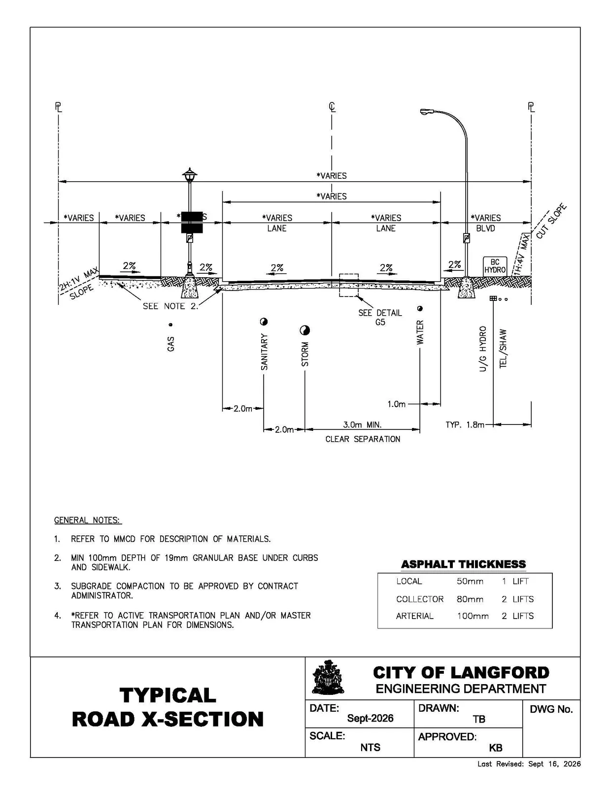
Drawing annotations
- Property lines: PL; centerline: CL.
- Dimensions marked *VARIES, including *VARIES LANE and *VARIES BLVD.
- Pavement cross slopes: 2%.
- Side slopes: 2H:1V MAX SLOPE; 1H:1V MAX CUT SLOPE.
- See Note 2.
- See Detail G5.
- BC HYDRO.
- Underground utilities shown: GAS, SANITARY, STORM, WATER, U/G HYDRO, TEL/SHAW.
- Utility separation dimensions shown: 2.0m, 2.0m, 3.0m MIN. CLEAR SEPARATION, 1.0m, and TYP. 1.8m.
General Notes
- REFER TO MMCD FOR DESCRIPTION OF MATERIALS.
- MIN 100mm DEPTH OF 19mm GRANULAR BASE UNDER CURBS AND SIDEWALK.
- SUBGRADE COMPACTION TO BE APPROVED BY CONTRACT ADMINISTRATOR.
- *REFER TO ACTIVE TRANSPORTATION PLAN AND/OR MASTER TRANSPORTATION PLAN FOR DIMENSIONS.
Asphalt Thickness
| Road classification | Thickness | Lifts |
|---|---|---|
| LOCAL | 50mm | 1 LIFT |
| COLLECTOR | 80mm | 2 LIFTS |
| ARTERIAL | 100mm | 2 LIFTS |
Title Block
CITY OF LANGFORD
ENGINEERING DEPARTMENT
| Field | Information |
|---|---|
| DATE | Sept-2026 |
| DRAWN | TB |
| SCALE | NTS |
| APPROVED | KB |
| DWG No. |
Page 16
Extracted from: Attachment 1 - Proposed Subdivision and Development Servicing Bylaw, Amendment No. 28, Bylaw No. 2158, 2026