DocumentsAppendixSep 28, 2026Pages 29–57
CITY OF LANGFORD SUPPLEMENTARY SPECIFICATIONS; SUPPLEMENTARY SPECIFICATIONS MODIFICATIONS AND ADDITIONS TO THE MMCD SPECIFICATIONS
Contains Langford’s supplementary construction specifications and modifications to MMCD specifications, followed by related standard drawing schedules and drawing sheets. Topics include concrete, waterworks, storm and sanitary sewers, landscaping, and irrigation.
Key facts
- Includes Schedule 11 supplementary specifications and drawing references
- Concrete works include a minimum 7-day wet-curing requirement
- Storm and sanitary sewer inspection and testing requirements are specified
- Several listed drawings are added, amended, replaced, or deleted by Bylaw No. 2158
City of Langford — Supplementary Specifications
Contents
| Section | Paragraph | Title |
|---|---|---|
| 01 53 01 – Temporary Facilities | ||
| 31 23 17 – Rock Removal | 1.6 | Measurement for Payment |
| 31 23 17 – Rock Removal | 1.7 | Seismic Survey and Monitoring |
| 31 23 17 – Rock Removal | 1.8 | Inspection and Testing |
| 32 11 23 – Granular Base | 1.4.4 | Measurement for Payment |
| 03 30 20 – Concrete Walks, Curbs, and Gutters | 2.1.5 (1) | Hand-formed and Hand Placed Concrete |
| 03 30 20 – Concrete Walks, Curbs, and Gutters | 2.1.5 (2) | Extruded Concrete |
| 03 30 20 – Concrete Walks, Curbs, and Gutters | 2.1.7 | Evaporation Retardant |
| 03 30 20 – Concrete Walks, Curbs, and Gutters | 2.1.8 | Curing Agent |
| 03 30 20 – Concrete Walks, Curbs, and Gutters | 3.4.2 | Inspection |
| 03 30 20 – Concrete Walks, Curbs, and Gutters | 3.10 | Control Joints |
| 03 30 20 – Concrete Walks, Curbs, and Gutters | 3.12.1 | Finishing |
| 03 30 20 – Concrete Walks, Curbs, and Gutters | 3.12.9 | Finishing |
| 03 30 20 – Concrete Walks, Curbs, and Gutters | 3.14.1 | Protection |
| 03 30 20 – Concrete Walks, Curbs, and Gutters | 3.15.1 | Curing |
| 32 13 13 – Portland Cement Concrete Paving | 3.8.16 | Concrete Placement |
| 32 13 13 – Portland Cement Concrete Paving | 3.10.6 | Finishing |
| 32 13 13 – Portland Cement Concrete Paving | 3.12.1 | Curing |
| 33 11 01 – Waterworks | 2.0 | Products |
| 33 11 01 – Waterworks | 3.0 | Execution |
| 33 40 01 – Storm Sewers | 3.11.6 | Cleaning and Flushing |
| 33 40 01 – Storm Sewers | 3.12 | Inspection and Testing |
| 33 30 01 – Sanitary Sewers | 3.11.6 | Cleaning and Flushing |
| 33 30 01 – Sanitary Sewers | 3.12 | Leakage Testing – General |
| 33 30 01 – Sanitary Sewers | 3.18 | Video Inspection |
| 33 34 01 – Sewage Force Mains | 3.14.4 | Cleaning and Flushing |
Supplementary Specifications
Page 29–57
| Section | Subsection | Title | Supplementary Specifications |
|---|---|---|---|
| 01 53 01 – Temporary Facilities | Delete This Section | ||
| 31 23 17 – Rock Removal | 1.6 | Measurement for Payment | Add Clause 1.6.6 which reads: “Payment for trench rock will be by cubic metre. For measurement purposes, the volume of trench rock is defined as that amount below subgrade in areas of mass rock removal or below natural rock surface, extending down to 200 mm below the lowest designed pipe or service invert in the trench and having a width of 450 mm plus the overall external diameter or dimension of the service or services being installed. For two services in common trench this means the width of the two outside diameters, plus the separation between the pipes plus 450 mm. Payment for the excavation of structures shall extend 500 mm from the outside faces of the structure and shall extend to 200 mm below the lowest elevation of the structure.” |
| 31 23 17 – Rock Removal | 1.7 | Seismic Survey and Monitoring | In Paragraph 1.7.1 replace the Phrase “Contract Administrator” with “Contractor”. In Paragraph 1.7.2 replace the word “Owner” with the word “Contractor”. |
| 32 11 23 – Granular Base | 1.4 | Measurement for Payment | Revise Paragraph 1.4.1 to read: “Limit for payment to be to the face of curb as shown on the Standard Detail Drawings.” |
| 03 30 20 – Concrete Walks, Curbs and Gutters | 2.1.5 (1) | Hand-formed and Hand Placed Concrete | Revise Paragraph 2.1.5 (1) to read: “Hand-formed and hand-placed concrete: (1) Exposure Classification (CSA A23.1): C2 (2) Minimum Compressive Strength (@ 28 Days): 32 MPa (3) Maximum Water-Cementing Materials Ratio: 0.45 Nominal Maximum Aggregate Size: 20 mm” |
| 03 30 20 – Concrete Walks, Curbs and Gutters | 2.1.5 (2) | Extruded Concrete | Revise Paragraph 2.1.5 (2) to read: “Extruded concrete: (1) Exposure Classification (CSA A23.1): C2 (2) Minimum Compressive Strength (@ 28 Days): 32 MPa (3) Maximum Water-Cementing Materials Ratio: 0.45 Nominal Maximum Aggregate Size: 14 mm or 10 mm” |
| 03 30 20 – Concrete Walks, Curbs and Gutters | 2.1.7 | Evaporation Retardant | Add Clause 2.1.7, which reads: “Evaporation Retardant: Liquid applied, water-diluted, emulsion intended to be applied to plastic concrete to limit moisture loss from the concrete during finishing operations.” |
| 03 30 20 – Concrete Walks, Curbs and Gutters | 2.1.8 | Curing Agent | Add Clause 2.1.8, which reads: “Curing Agent: Liquid applied, membrane forming, curing compound intended for application to concrete following completion of finishing operations. Product shall meet or exceed the requirements of the most recent version of ASTM C309, or as otherwise approved by the City Engineer.” |
| 03 30 20 – Concrete Walks, Curbs and Gutters | 3.4.2 | Inspection | Add Clause 3.4.2, which reads: “Contractor shall review available local weather prediction models to determine if adverse weather conditions are expected during the concrete placement or curing periods. If Hot Weather or Cold Weather conditions, as defined below are expected, the contractor shall have all necessary equipment for protection and curing on site prior to the start of concrete placement. Hot Weather is defined by the American Concrete Institute (ACI) as: One or a combination of the following conditions that tends to impair the quality of freshly mixed or hardened concrete by accelerating the rate of moisture loss and rate of cement hydration or otherwise causing detrimental results: high ambient temperature; high concrete temperature; low relative humidity; and high wind speed. Cold Weather is defined by the American Concrete Institute (ACI) as: When air temperature has fallen to, or is expected to fall, below 4°C during the protection period; protection period is defined as the time recommended to prevent concrete from being adversely affected by exposure to cold weather during construction.” |
| 03 30 20 – Concrete Walks, Curbs and Gutters | 3.10 | Control Joints | Revise Paragraph 3.10.1 to read: “In sidewalks only, ‘Zip strip’ to be installed as control joints at maximum 3 m intervals.” |
| 03 30 20 – Concrete Walks, Curbs and Gutters | 3.12.1 | Finishing | Revise Clause 3.12.1 to read: “Commence with finishing operations only once the concrete has achieved initial set. Initial set may be measured on site with a concrete set penetrometer or can be estimated from previous time of set measurements. Time of set estimates shall include allowance for the inclusion of set retarders or hydration stabilizers in the concrete mix. Finish surface of concrete sidewalks and utility strips to smooth surface with magnesium or wood float and brush or broom to provide uniform non-skid surface.” |
| 03 30 20 – Concrete Walks, Curbs and Gutters | 3.12.9 | Finishing | Add Clause 3.12.9 to read: “The contractor shall not add any water to the concrete surface during the finishing process.” |
| 03 30 20 – Concrete Walks, Curbs and Gutters | 3.14.1 | Protection | Revise Clause 3.14.1 to read: “The concrete shall be protected from premature drying with the use of environmental controls, such as windbreaks, shading, or fogging, when rapid surface drying conditions are expected. The contractor shall also use an evaporation retardant to reduce surface moisture loss; however, these products shall be applied per the manufacturer’s written instructions and shall not be used as finishing aids. Protect freshly finished concrete from dust, rain or frost by using tarpaulins or other suitable protective coverings.” |
| 03 30 20 – Concrete Walks, Curbs and Gutters | 3.15.1 | Curing | Revise Clause 3.15.1 to read: “All concrete works shall be wet cured for a minimum of 7-days in conformance with CSA A23.1:24, Table 19, curing regime 3. Allowable curing regimes shall include continuous sprinkling, or saturated lint-free fabric geotextile with polyethylene sheeting covering. Curing shall be installed as soon as final finishing is complete, and the curing system will not mar the surface of the concrete. The curing system shall be continuous throughout the curing period. Alternative curing systems, other than those listed above, shall be submitted to the City for review and approval.” |
| 32 13 13 – Portland Cement Concrete Paving | 3.8.16 | Concrete Placement | Add Clause 3.8.16, which reads: “The concrete shall be protected from premature drying with the use of environmental controls, such as windbreaks, shading, or fogging, when rapid surface drying conditions are expected. The contractor shall also use an evaporation retardant to reduce surface moisture loss; however, these products shall be applied per the manufacturer’s written instructions and shall not be used as finishing aids.” |
| 32 13 13 – Portland Cement Concrete Paving | 3.10.6 | Finishing | Revise Clause 3.10.6 to read: “Commence with finishing operations only once the concrete has achieved initial set. Initial set may be measured on site with a concrete set penetrometer or can be estimated from previously documented time of set measurements for the utilized concrete mix. Time of set estimates shall include allowance for the inclusion of set retarders or hydration stabilizers in the concrete mix. Finish surface of concrete to smooth surface with magnesium or wood float and brush or broom to provide uniform non-skid surface.” |
| 32 13 13 – Portland Cement Concrete Paving | 3.12.1 | Curing | Delete Clause 3.12.1, and replace with: “Complete curing is accordance with Specification Section 03 30 20 – Concrete Walks, Curbs, and Gutters, Clause 3.15 Curing.” |
| 33 11 01 – Waterworks | 2.0 | Products | Delete these sections and replace with (C.R.D. Water Department) Engineering Specifications and Standard Drawings. |
Supplementary Specifications — Continued
Page 29–57
| Section | Subsection | Title | Supplementary Specifications |
|---|---|---|---|
| 33 40 01 – Storm Sewers | 3.10 | Service Connection Installation | Delete the first 2 words of “Where specified,” from Paragraph 3.10.3 to read “Install inspection chambers at, etc.” |
| 33 40 01 – Storm Sewers | 3.11 | Cleaning and Flushing | Revise Paragraph 3.11.6 to read: “Remove foreign material from pipe and related appurtenances by power flushing with water.” Delete the remainder of the Paragraph. |
| 33 40 01 – Storm Sewers | 3.12 | Inspection and Testing | In 3.12.1 replace the phrase “under 900mm in diameter.” with “prior to Acceptance of Works and services and prior to Final Acceptance of works and services.” Add Clause 3.12.4 which reads: “The Contractor shall carry out power flushing and video inspection of all storm sewers. The results of the inspection shall be delivered to the Contract Administrator at least 14 days prior Acceptance of Works and services and prior to Final Acceptance of works and services. Inspection records shall illustrate flow through the pipe for all design grades less than 2%.” Add Clause 3.12.5 which reads: “The inspection record shall be in a form acceptable to the City.” Add Clause 3.12.6 which reads: “Inspection video shall be submitted to the City in electronic format.” |
| 33 30 01 – Sanitary Sewers | 3.11 | Cleaning and Flushing | Revise 3.11.6 to read: “Remove foreign material from pipe and related appurtenances by power flushing with water.” Delete the remainder of the paragraph. |
| 33 30 01 – Sanitary Sewers | 3.12 | Leakage Testing General | The preferred method of leakage testing is the low pressure air test. All other tests will be carried out at the discretion of the Contract Administrator. |
| 33 30 01 – Sanitary Sewers | 3.18 | Video Inspection | Revise Paragraph 3.18.1 replace the phrase “under 900mm in diameter following completion of installation” with “prior to Acceptance of Works and services and prior to Final Acceptance of works and services.” Add Clause 3.18.3 which reads: “Inspection records shall illustrate flow through the pipe for all design grades less than 2%.” Add Clause 3.18.4 which reads: “The inspection report shall be in a form acceptable to the City.” Add Clause 3.18.5 which reads: “Inspections shall be submitted to the City in electronic format.” Add Clause 3.18.6 which reads: “Prior to the end of the maintenance period, or when directed by the Contract Administrator, the Contractor is to carry out power flushing and video inspection of all mains. The results of the inspection are to be delivered to the Contract Administrator at least 14 days prior to the end of the maintenance period.” |
| 33 34 01 – Sewage Force Mains | 3.14 | Cleaning and Flushing | Revise Paragraph 3.14.4 to read: “Remove foreign material from pipe and related appurtenances by mandrelling or swabbing.” |
Page 29–57
Supplementary Specifications — Modifications and Additions to the MMCD Specifications
| Drawing No. | Title | Supplement |
|---|---|---|
| B1 | Banner Sizes | Add this drawing (Bylaw 1669) |
| C1 | Concrete Sidewalk, Infill and Barrier Curb | Delete this drawing (Bylaw 1000) |
| C2 | Concrete Sidewalk and Barrier Curb | Delete this drawing (Bylaw 1000) |
| C3 | Concrete Sidewalk and Rollover Curb | Delete this drawing (Bylaw 1000) |
| C6 | Concrete Median Curb and Interim Curbs | Delete this drawing and refer to Drawing No. SS C6 “Curb and Gutter Detail”. (Bylaw 1000) |
| C8 | Wheelchair Ramp for Sidewalk, Infill and Barrier Curb | Delete this drawing and refer to Drawing No. SSC8, titled “Sidewalk Ramp (Boulevard Adjacent to Curb)”. (Bylaw 1000) |
| C9 | Wheelchair Ramp for Sidewalk and Barrier Curbs | Delete this drawing and refer to Drawing No. SSC9, titled “Sidewalk Ramp (Sidewalk Adjacent to Curb)”. (Bylaw 1000) |
| C15 | Driveway Configurations | Replace drawing C15 with new C15 (Bylaw 1574) |
| E1 | Double Headed Streetlight | Add this drawing (Bylaw 1000) |
| E2 | Single Head Lumca Prestige | Replace with new E2 (Bylaw 2103) |
| E3 | Cyclone Streetlight | Replaced with drawing E8 (Bylaw 1618) |
| E4 | Cyclone Streetlight Base | Replaced with drawing E9 (Bylaw 1618) |
| E5 | Landscaping Outlet Post | Add this drawing (Bylaw 1000) |
| E6 | Waste Receptacle Kiosk | Add this drawing (Bylaw 1000) |
| E7 | Cobra Street Light | Replaced with drawing E10 (Bylaw 1618) |
| E8 | Langford Post Top Luminaire | Amend this drawing (Bylaw 1669) |
| E9 | Langford Post Top Luminaire Service Base | Added Bylaw 1618 |
| E10 | Cobra Street Lighting | Amend this drawing (Bylaw 1669) |
| G1 | General Legend for Contract Drawings | Delete this drawing and refer to Contract Drawing Legends. (Bylaw 1000) |
| G2 | Legends for Materials | Delete this drawing. (Bylaw 1000) |
| G3 | Legend for Streetlight and Traffic Signal Drawings | Delete this drawing and refer to Contract Drawing Legends. (Bylaw 1000) |
| G4 | Utility Trench | Amend this drawing (Bylaw 1817) |
| G5 | Pavement Restoration | Amend this drawing (Bylaw 1817) |
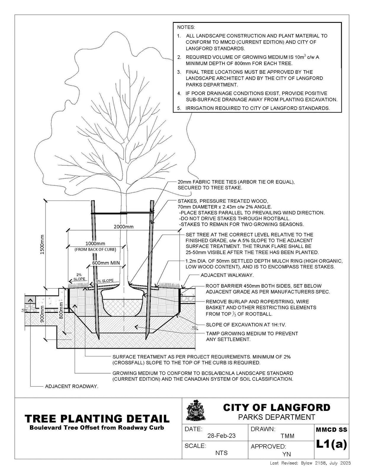
| L1(a) | Street Tree Planting Detail | Replace with new L1(a) (Bylaw 2158) |
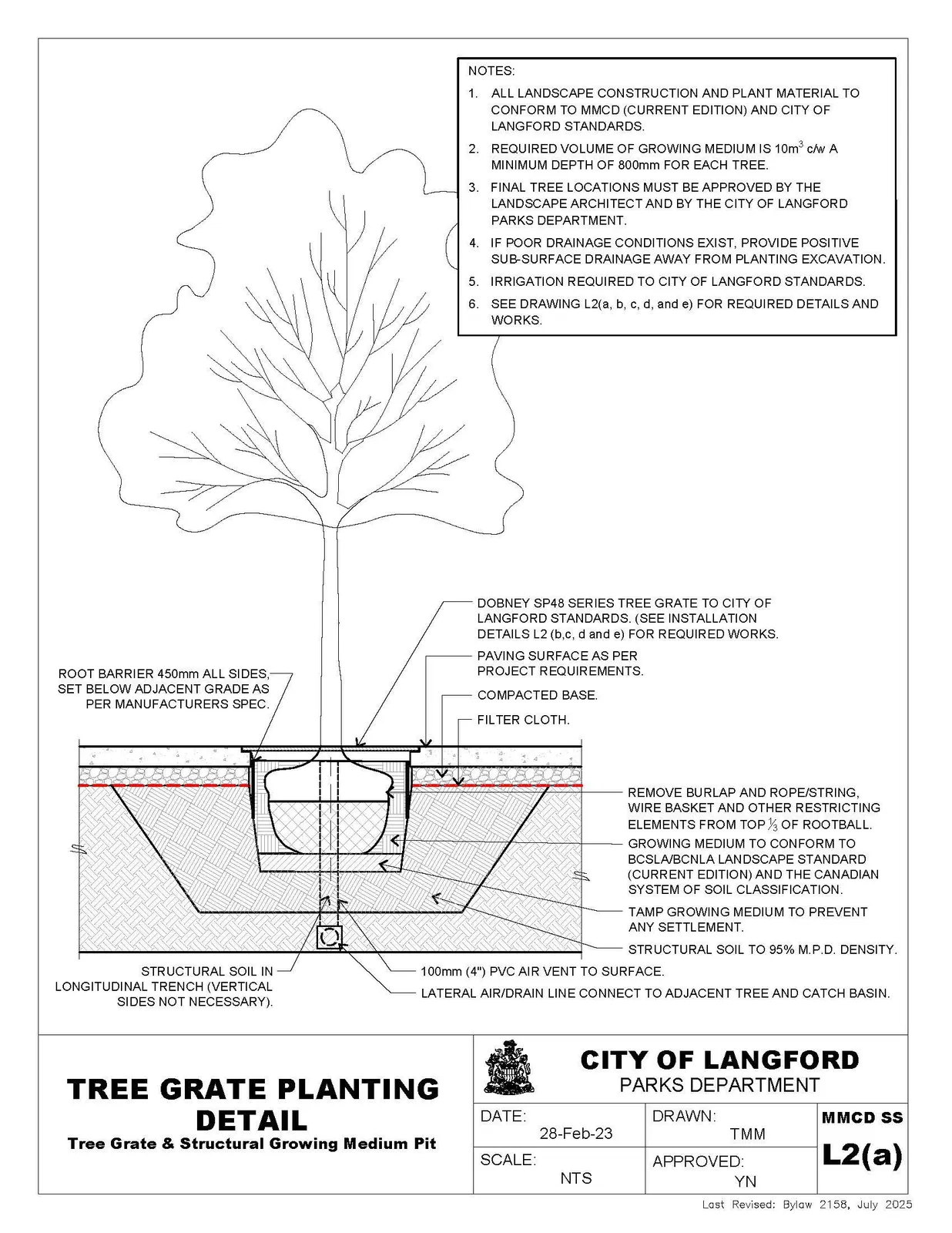
| L2(a) | Tree Grate Planting Detail | Replace with new L2(a) (Bylaw 2158) |
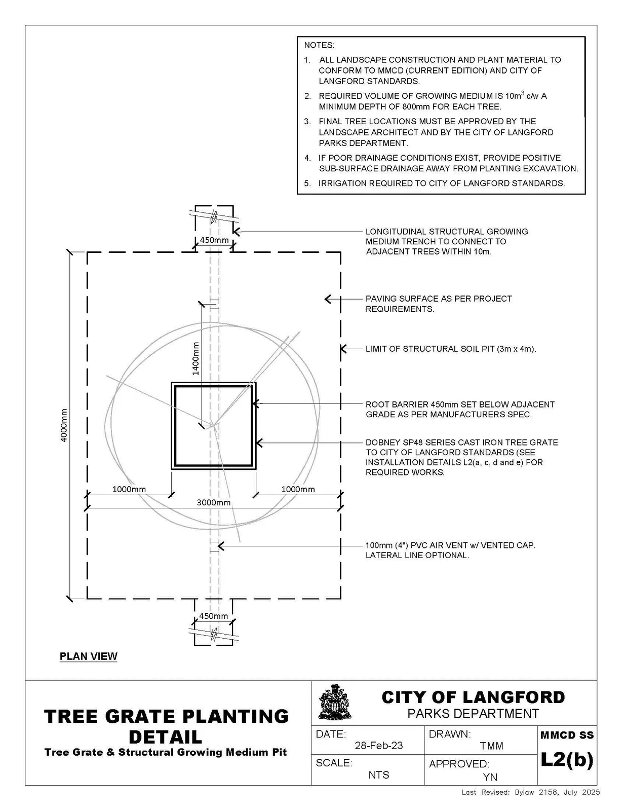
| L2(b) | Tree Grate Planting Detail | Replace with new L2(b) (Bylaw 2158) |
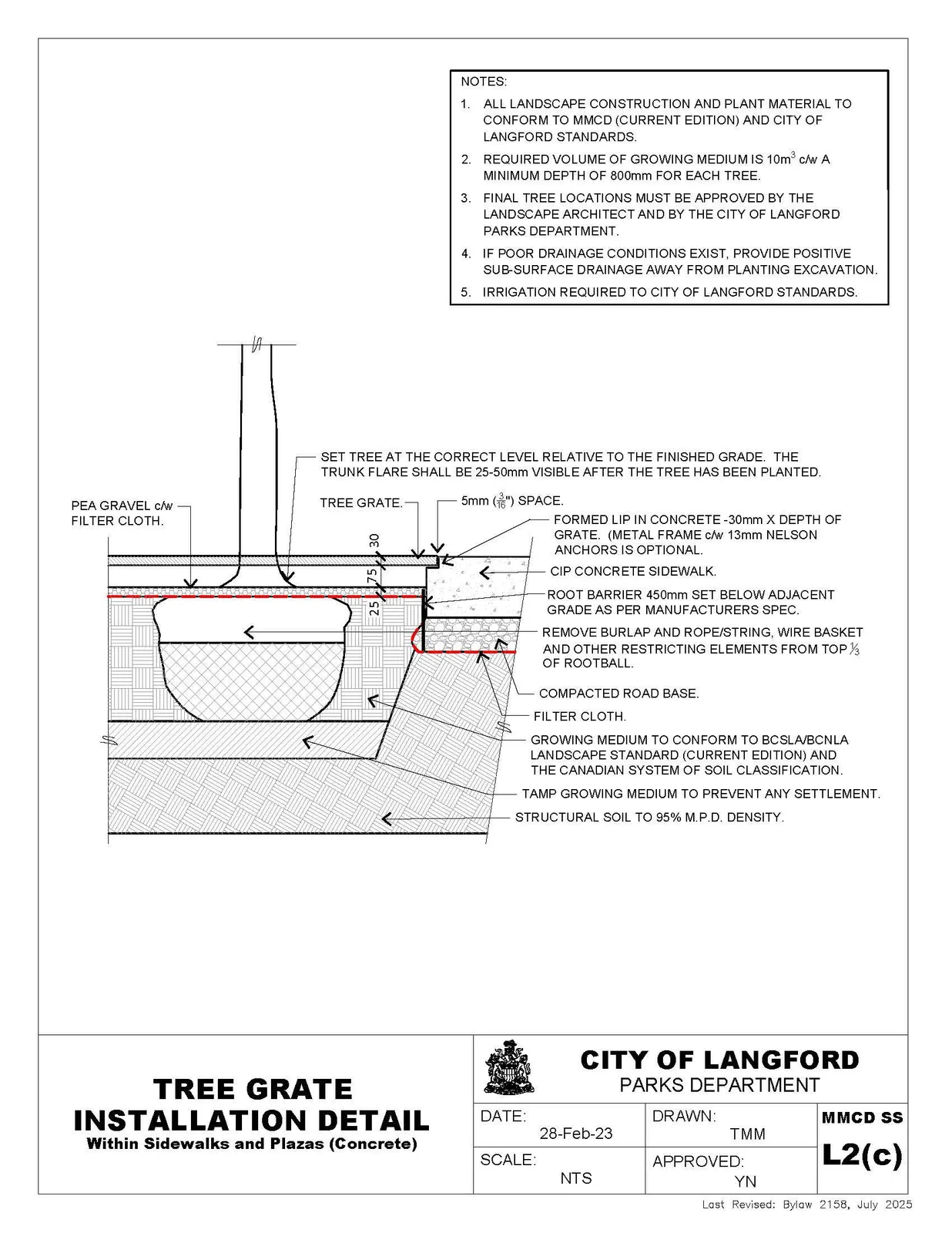
| L2(c) | Tree Grate Installation Detail | Replace with new L2(c) (Bylaw 2158) |
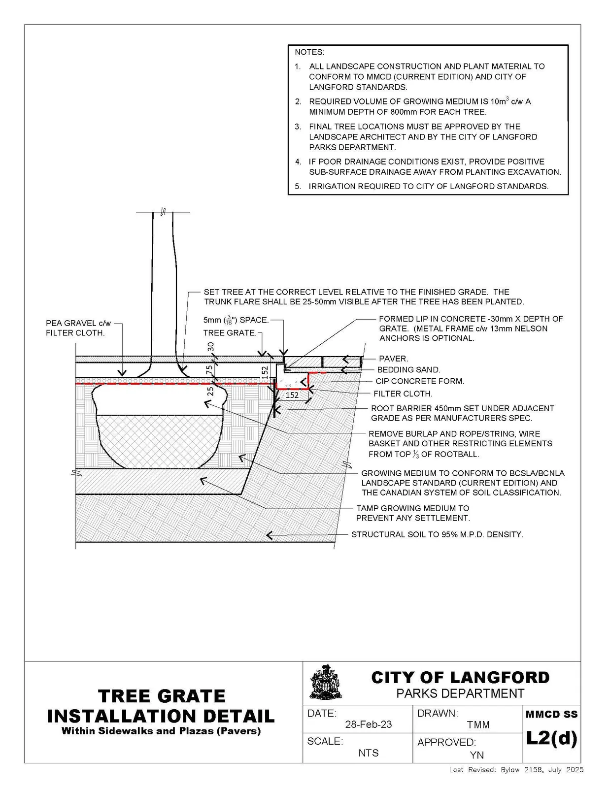
| L2(d) | Tree Grate Installation Detail | Replace with new L2(d) (Bylaw 2158) |
| L2(e) | Tree Grate Detail Specification | Replace with new L2(e) (Bylaw 2103) |
| L2(fa) | Artificial Turf Installation at Boulevard Tree | Delete this drawing (Bylaw 2158) |
| L2(fb) | Artificial Turf Installation at Boulevard Tree | Delete this drawing (Bylaw 2158) |
| L2(g) | Artificial Turf at Concrete | Delete this drawing (Bylaw 2158) |
| L2(h) | Artificial Turf Installation | Delete this drawing (Bylaw 2158) |
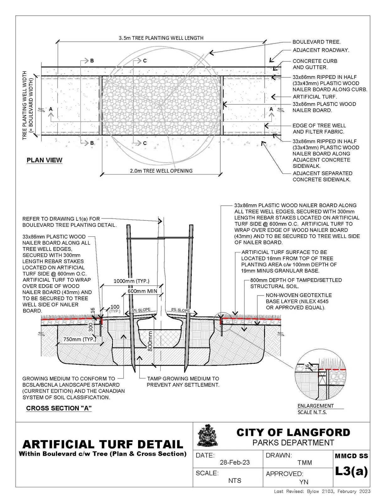
| L3(a) | Artificial Turf Detail | Add this drawing (Bylaw 2158) |
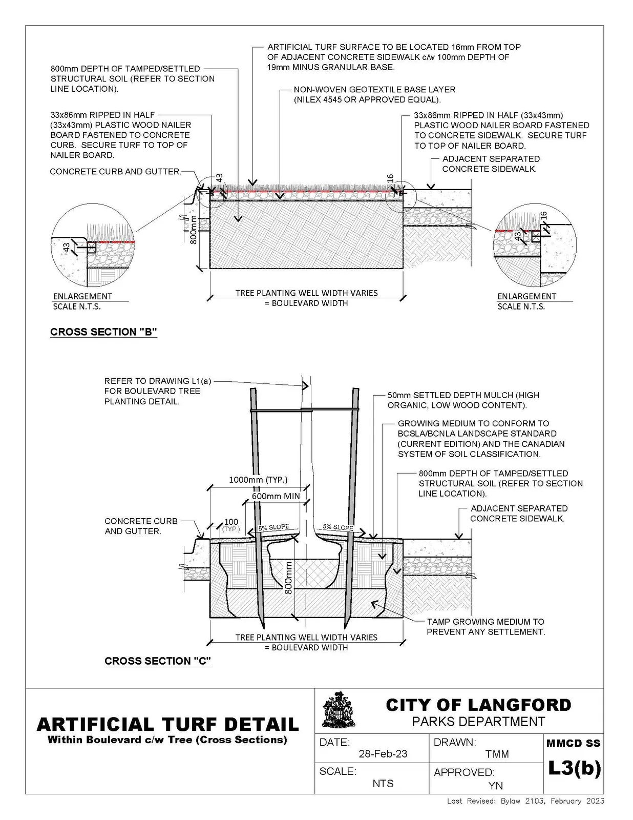
| L3(b) | Artificial Turf Detail | Add this drawing (Bylaw 2158) |
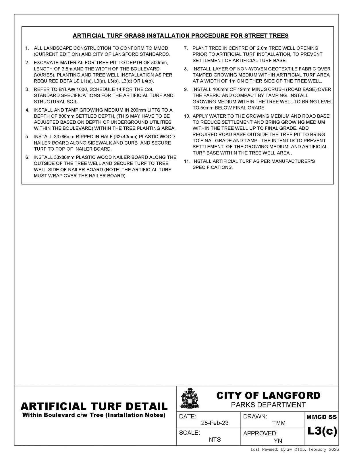
| L3(c) | Artificial Turf Detail | Add this drawing (Bylaw 2158) |
| L3(d) | Artificial Turf Detail | Add this drawing (Bylaw 2158) |
| L3(e) | Artificial Turf Detail | Add this drawing (Bylaw 2158) |
| L4 | Median Planting | Delete this drawing (Bylaw 2158) |
| L4(a) | Median Planting Detail | Replaced with new L4(a) (Bylaw 2158) |
| L4(b) | Median Planting Detail | Add this drawing (Bylaw 2103) |
| L6(a) | Sod Installation Detail | Add this drawing (Bylaw 2103) |
| L6(b) | Seed Installation Detail | Add this drawing (Bylaw 2103) |
| L7 | Split Rail Fence Detail | Add this drawing (Bylaw 2103) |
| P1 | Municipal Irrigation Sleeving Detail | Replace with new P1 (Bylaw 2103) |
| P2 | Municipal Irrigation Sleeving Detail | Replace with new P2 (Bylaw 2103) |
| P3 | Municipal Irrigation Sleeving Detail | Replace with new P3 (Bylaw 2103) |
| P4 | Municipal Irrigation Sleeving Detail | Replace with new P4 (Bylaw 2103) |
| P5 | Water Connection | Replaced with new P5 (Bylaw 2158) |
| P5(a) | Irrigation Detail | Add this drawing (Bylaw 2103) |
| P5(b) | Irrigation Detail | Add this drawing (Bylaw 2103) |
| P6 | Valve Manifold | Add this drawing (Bylaw 1000) |
| P6(a) | Irrigation Detail | Add this drawing (Bylaw 2103) |
| P7 | Drip Line | Replace with new P7 (Bylaw 1292) |
| P7(a) | Irrigation Detail | Add this drawing (Bylaw 2158) |
| P8(a) | Irrigation Detail | Add this drawing (Bylaw 2103) |
| P8(b) | Irrigation Detail | Add this drawing (Bylaw 2103) |
| P9 | Irrigation Detail | Add this drawing (Bylaw 2103) |
| P10 | Irrigation Detail | Add this drawing (Bylaw 2103) |
| P11 | Irrigation Detail | Replace with new P11 (Bylaw 2158) |
| P12 | Irrigation Detail | Replace with new P12 (Bylaw 2158) |
| P13 | Irrigation Detail | Add this drawing (Bylaw 2103) |
| P14 | Irrigation Detail | Add this drawing (Bylaw 2103) |
| P15 | Irrigation Detail | Add this drawing (Bylaw 2103) |
| RS1 | Turn Around Details | Amend this drawing (Bylaw 1817) |
| RS2 | Turn Arounds | Amend this drawing (Bylaw 1817) |
| RS3 | Temporary Turn Arounds | Add this drawing (Bylaw 1000) |
| RS4 | Pedestrian Activated Crosswalk Signals | Replace with new RS4 (Bylaw 2103) |
| RS5 | Canada Post Mailbox Pull Out | Replace with new RS5 (Bylaw 2103) |
| S4 | Inside Drop Manhole | Delete this drawing (Bylaw 1000) |
| S6 | Sewer Cleanout | Delete this Drawing and refer to Drawing No. SSS6 “Sewer Cleanout”. (Bylaw 1000) |
| S9 | Inspection Chamber for 100 to 200 Sanitary Sewer Connection | Amend this drawing (Bylaw 1817) |
| S10 | Double Catch Basin | Add this drawing (Bylaw 1494) |
| S11 | Top Inlet Catch Basin | Amend this Drawing (Bylaw 1669) |
| S15 | Driveway Culvert with Concrete Block Endwalls | Delete this drawing (Bylaw 1817) |
| S16 | Ditch Inlet | Add this Drawing to Standard Detail Drawings under “Storm and Sanitary Sewers” (Bylaw 1000) |
| S17 | Sanitary Force Main Connection | Add this drawing (Bylaw 1000) |
| SD1 | Stormwater Control and Treatment Areas | Add this drawing (Bylaw 1000) |
| SD2 | Drainage Calculation Sheet | Add this drawing (Bylaw 1000) |
| SD3 | Langford Rainfall Intensity-Duration Frequency Curve | Add this drawing (Bylaw 1000) |
| SD4 | Lot Development Erosion and Sediment Control | Add this drawing (Bylaw 1000) |
| SD5 | Silt Fence | Add this drawing (Bylaw 1000) |
| SD6 | Sediment Basin | Add this drawing (Bylaw 1000) |
| SD7 | Vertical Seepage Pit Detail | Replace with new SD7 (Bylaw 2158) |
| SD8 | Combined Constructed Wetland and Detention Facility | Add this drawing (Bylaw 1000) |
| SD9 | Grass Swale | Add this drawing (Bylaw 1000) |
| SD10 | Filter Strip | Add this drawing (Bylaw 1000) |
| SD11 | Oil/Grit Separator Chamber with External High Flow Bypass | Add this drawing (Bylaw 1000) |
| SD12 | Oil/Grit Separator Type 1 | Add this drawing (Bylaw 1000) |
| SD13 | Oil/Grit Separator Type 2 | Add this drawing (Bylaw 1000) |
| SD14 | Flow Control Manhole | Add this drawing (Bylaw 1000) |
| SD15 | Combined Detention for 2 Year Control & Oil/Grit Separator | Add this drawing (Bylaw 1000) |
| SD16 | Storage and Outlet Sizing | Add this drawing (Bylaw 1000) |
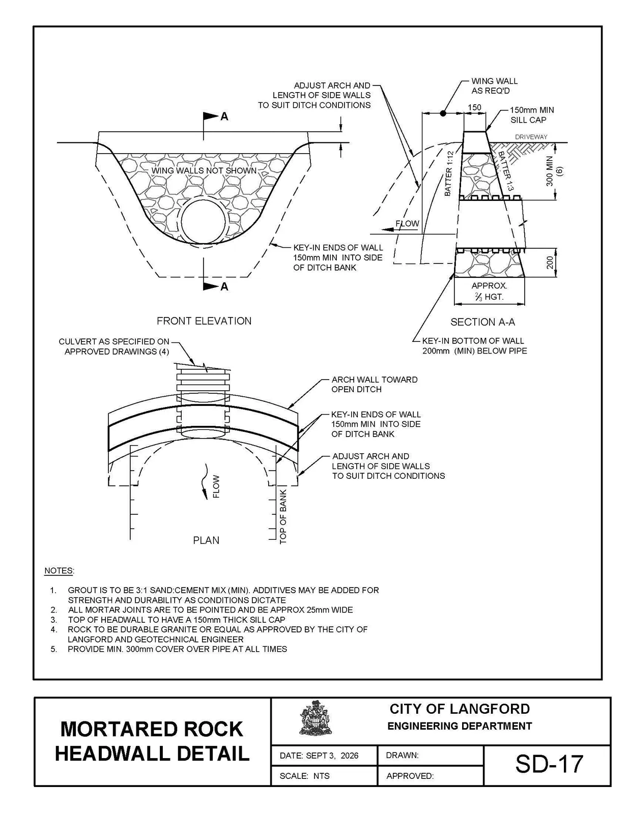
| SD17 | Mortared Rock Headwall | Add this drawing (Bylaw 2158) |
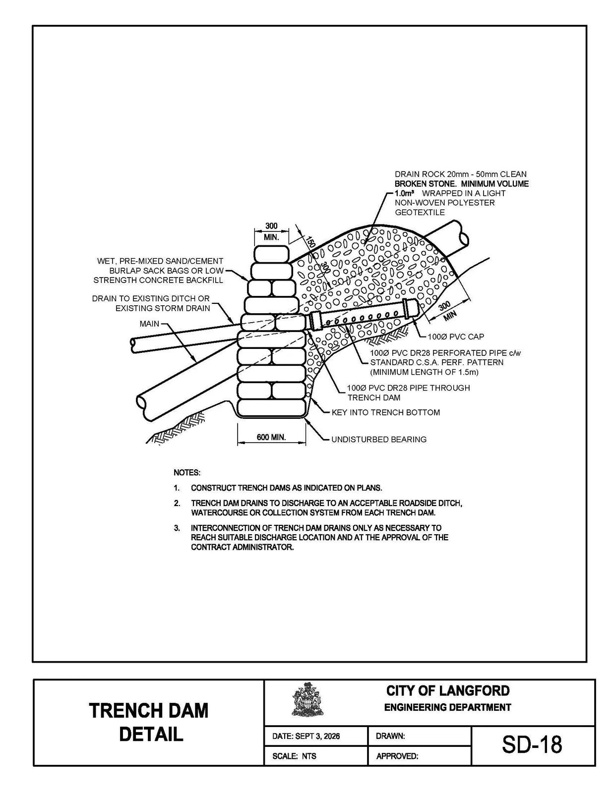
| SD18 | Trench Dam | Add this drawing (Bylaw 2158) |
| W1 | Fire Hydrant Clearance Specifications | Add this drawing (Bylaw 1513) |
Page 29–57
Standard Detail Drawings
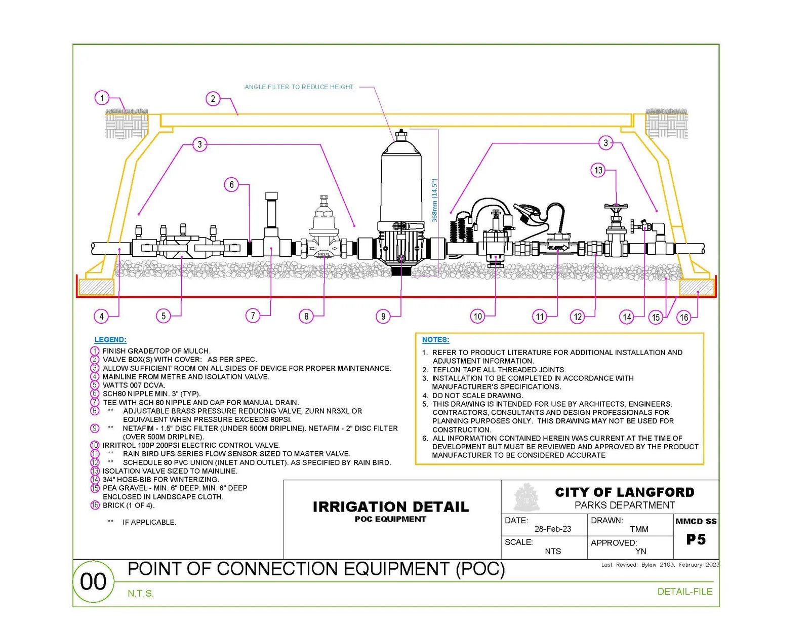
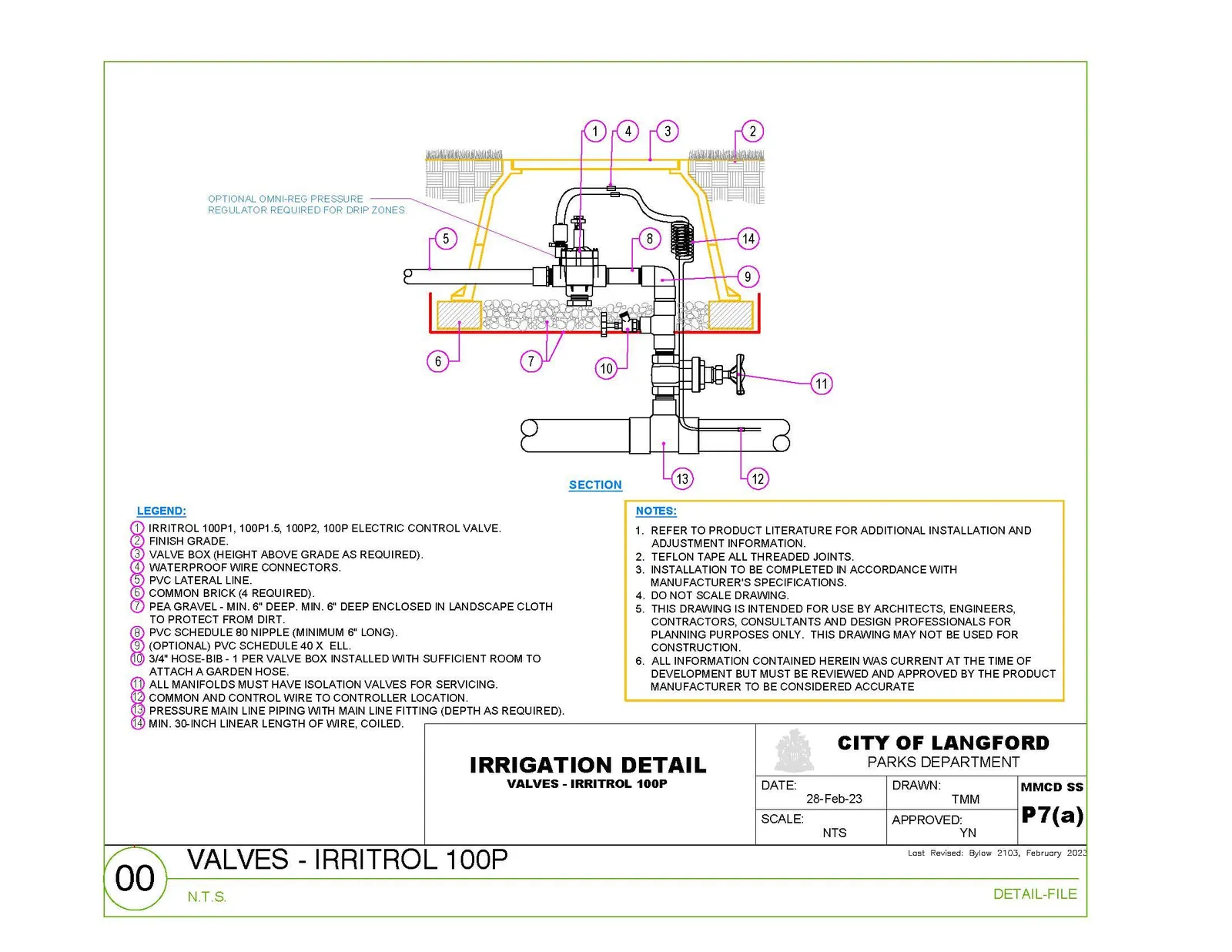
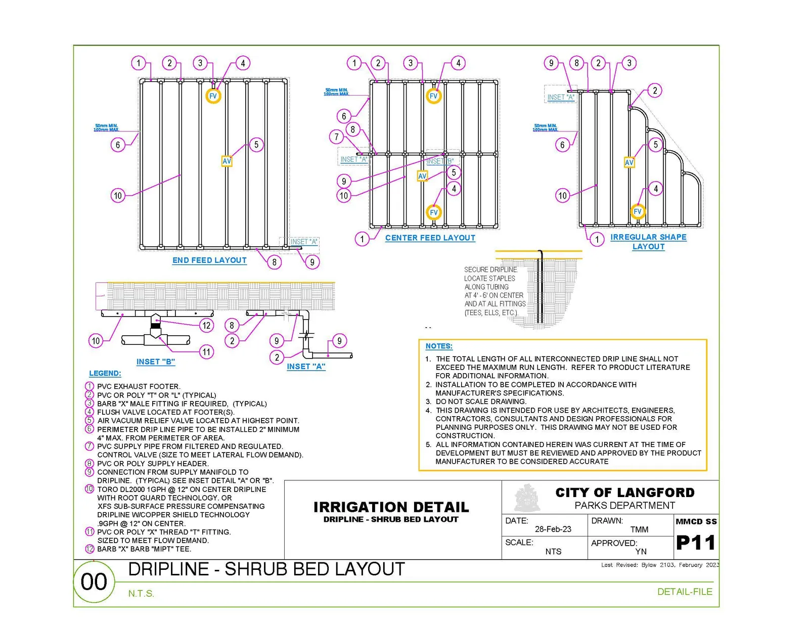
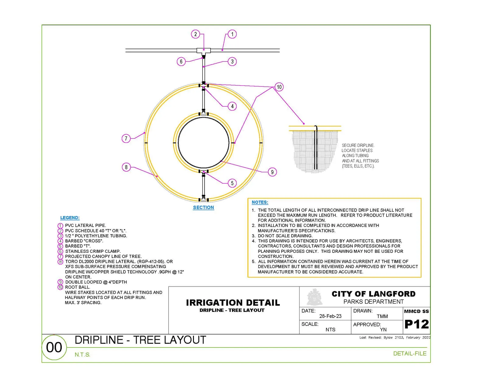
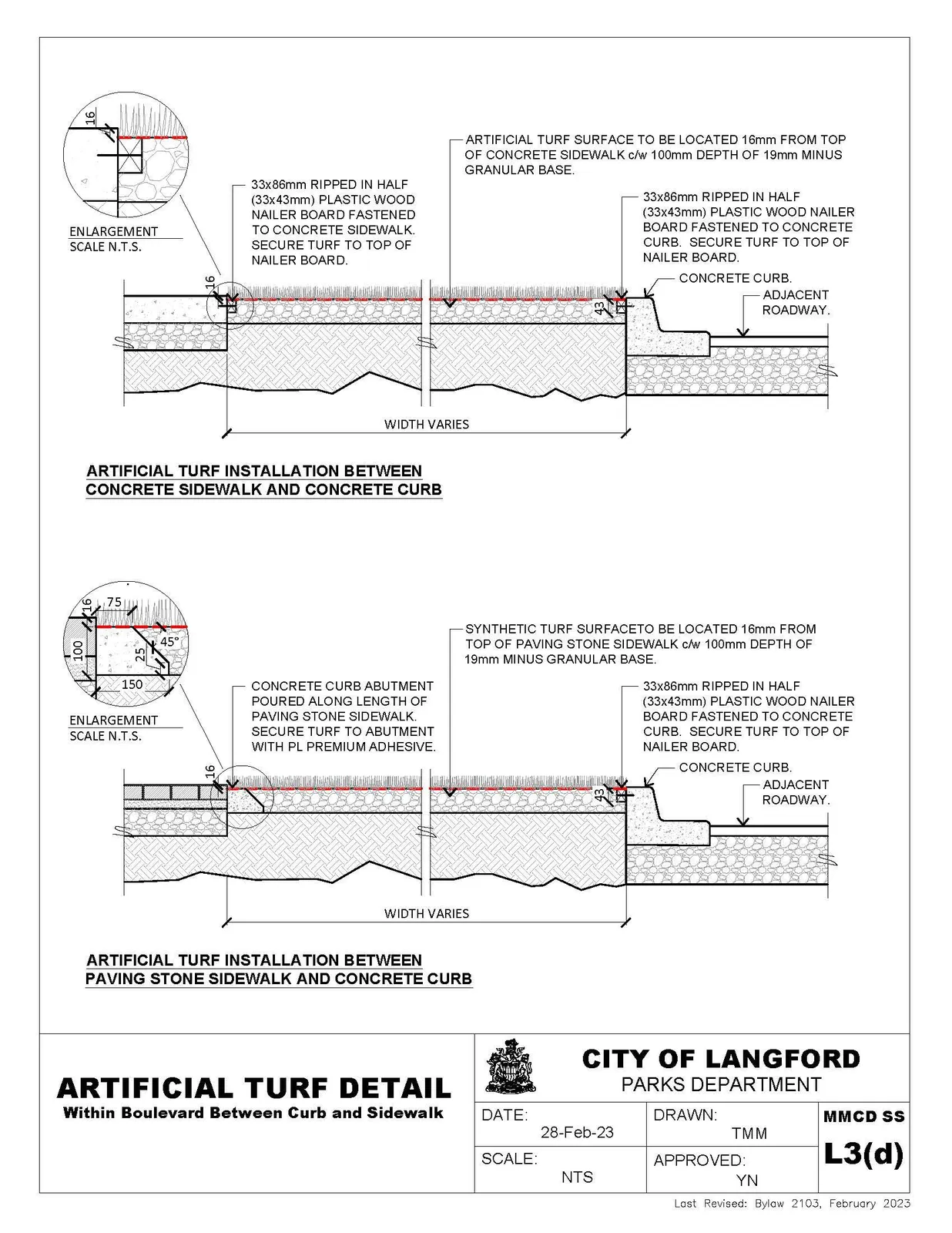
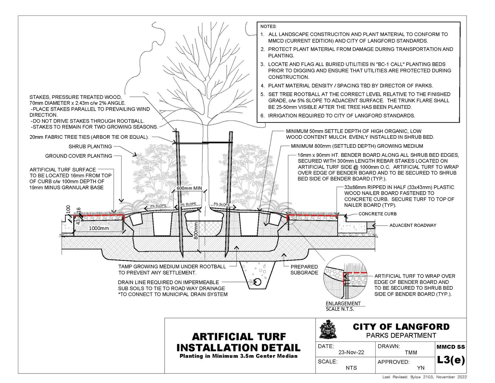
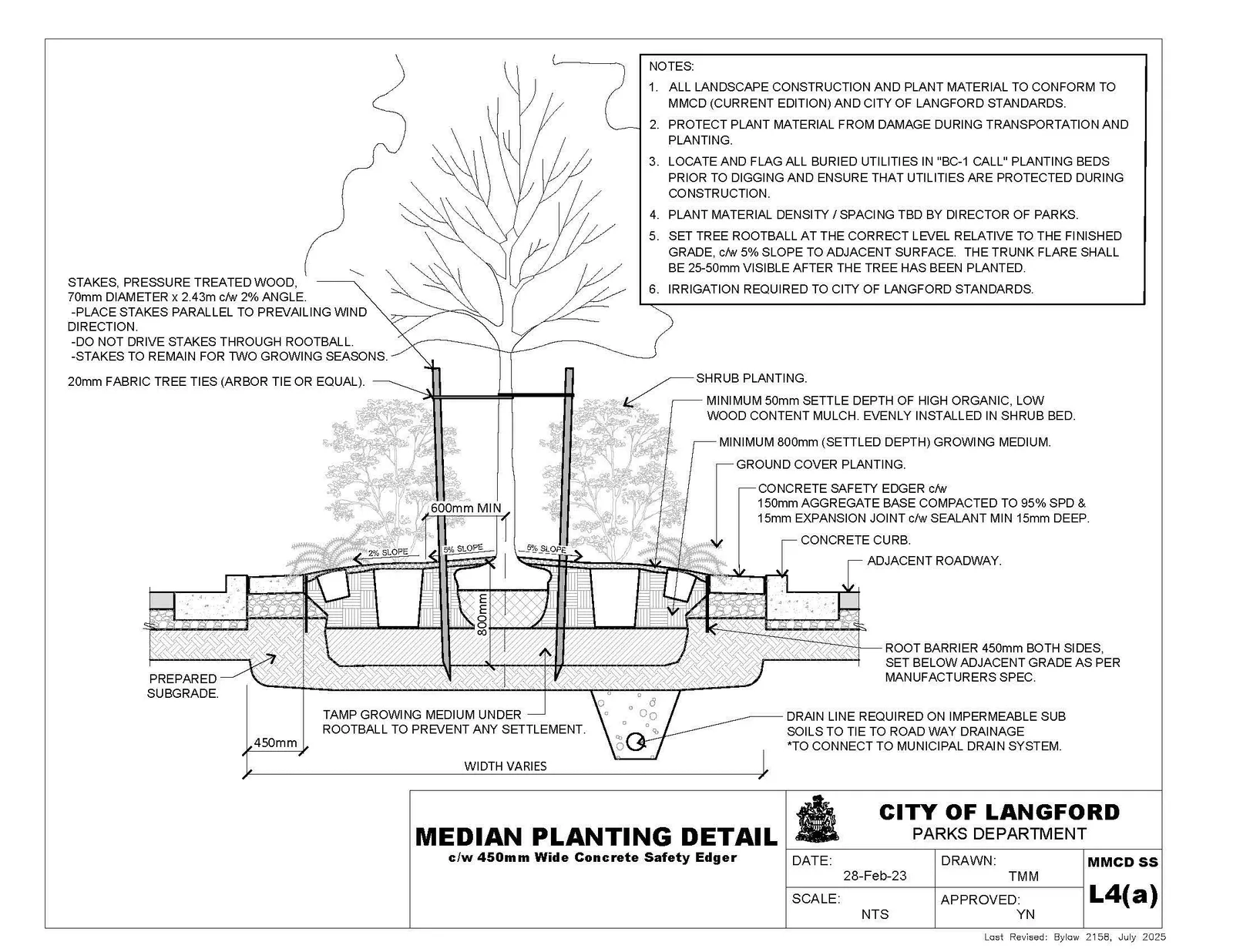
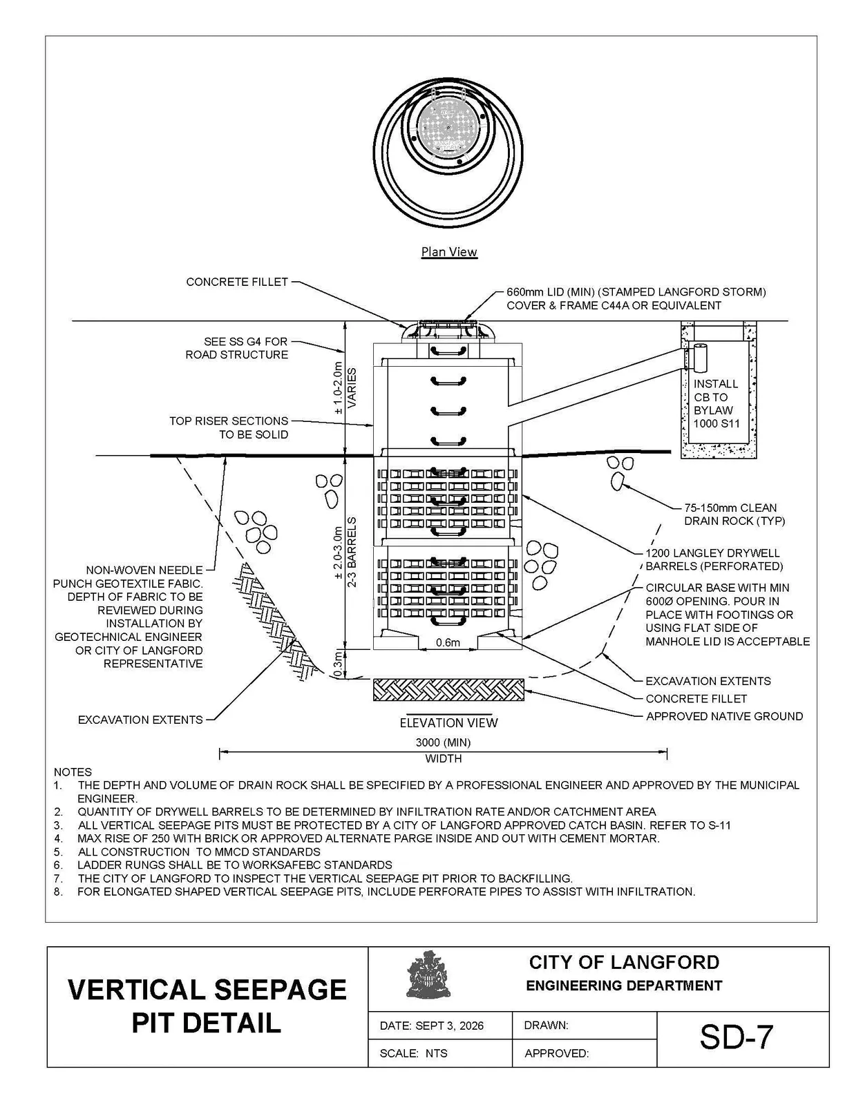
Page 29–57
Extracted from: Attachment 1 - Proposed Subdivision and Development Servicing Bylaw, Amendment No. 28, Bylaw No. 2158, 2026